.webp?length=400&name=Cyber-Radio-NDR585%20(3).webp)


.webp?width=70&height=70&name=Vector%20(1).webp)

Lexi Jones|06/08/26
06/19/20
If you are an RF engineer supporting government-focused mission requirements, you have probably at least considered the implications of moving toward compliance with the Sensor Open System Architecture (SOSA). If your responsibilities include signal intelligence (SIGINT), electronic warfare (EW), radar, and communications, then you are likely well on your way down this path already. We recently covered some background on SOSA and how it intersects the world of software defined radio (SDR) here. In this blog, we will take a look at some of the basics of RF I/O and how these I/O signals are expected to be deployed according to SOSA. We will work through the entire signal chain from the antenna to the chassis/backplane and finally to the RF transceiver card installed in the system.
Where is My Antenna?
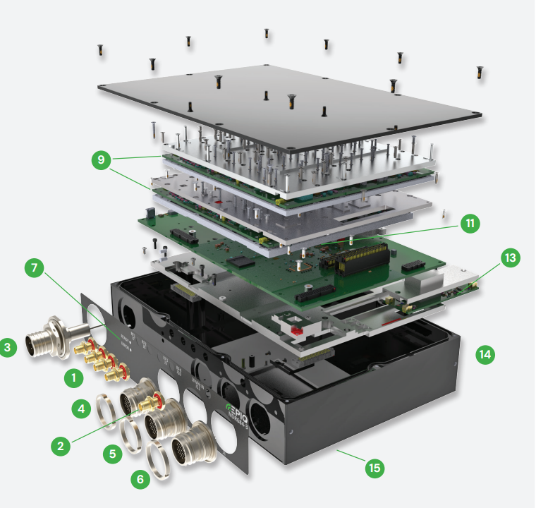
Beyond just designing radios and processing cards for a particular application, there are expectations for how RF signals enter and exit a SOSA-aligned system. Every RF transceiver requires an antenna, but how the antenna connects up to a SOSA-aligned platform might be something you haven’t given much thought to. There are the same familiar radio system components you would expect to see: antennas, filters/amplifiers, and 3U/6U VPX plug in cards (PICs) for RF transceivers and signal processing. But there is also a SOSA-aligned chassis, with a backplane consisting of one or more SOSA-aligned I/O profiles for modular hardware just like a traditional box instrument. SOSA leverages VITA’s OpenVPX architecture to define both the chassis and the slot profiles for plug-in cards, with the goal of developing systems faster through vendor interoperability. This means future features can be added to RF systems by swapping cards in and out instead of expensive and time consuming hardware upgrades.

Fig. 1: A typical system-level block diagram for a SOSA-aligned processing system
But what about the antenna? In defense applications, an antenna might be attached directly to a vehicle such as a tank or an F-16. The antenna may actually consist of multiple elements with each element covering a different range of RF frequencies. The frequency range covered by these antennas typically start around 2 MHz and go all the way to 18 GHz  and beyond (up to 40 GHz to support 5G deployments in the FR2 band). Further, applications such as beamforming, beamsteering, and direction-finding typically require multiple antennas. As the number of antennas increases, so does the routing complexity to ensure that the RF signals of interest can be transferred into the SOSA chassis with minimal signal degradation.
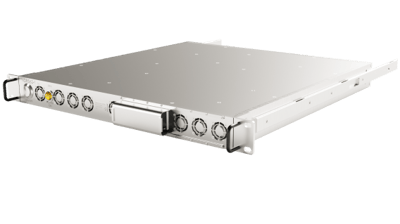
SOSA recognizes that the integration of an antenna in a system will be tailored to the particular platform on which it’s being deployed. Further, an antenna (or multiple antennas) may go through some level of RF conditioning in order to provide filtering and/or amplification prior to the sensor chassis. This RF conditioning may be specific to the platform and is not typically defined by SOSA. A low-loss RF coaxial cable connection from the antenna and/or conditioning hardware then gets routed into the SOSA chassis through one or more RF connector ports, and this is where SOSA begins specifying system components. A SOSA-aligned chassis would typically include one or more “J8” RF connectors and/or one or more “J9” RF connectors. The receptacle for the RF connector port designated as “J8” is a 20-pin high density RF connector utilizing an MIL-DTL-38999 size 12 socket with SMPM pin connectors. The receptacle for the RF connector port designated as “J9” is an 8-pin low loss RF connector utilizing a MIL-DTL-38999 size 8 socket with BMB pin connectors. Both of these RF connectors would be externally accessible on the sensor chassis and provide high signal fidelity to 50 GHz and 22 GHz, respectively.
The RF connector ports on the chassis typically connect directly to the SOSA backplane through a low-loss coaxial cable. From the backplane, these signals are distributed to the relevant 3U/6U card slot profiles where RF interfacing is allowed. VITA 67.3 defines the standard for the location of the RF I/O between the backplane and 3U/6U plug-in card, as well as the connector options. It is worth pointing out that VITA 67.3 is still evolving. VITA 67.3 allows for different apertures on the rear of the 3U/6U PIC, where RF or optical I/O between the PIC and the backplane can be utilized. For a 3U backplane, the J2 position is typically where the VITA 67.3 aperture is located. For a 6U backplane, J2, J3, J4, J5, or J6 may be utilized for the VITA 67.3 aperture. RF I/O connectors are available today which can fit up to 20 RF coaxial contacts in a full size VITA 67.3 module. The RF contacts utilized to date in deployed systems include SMPM, SMPS, and NanoRF™.
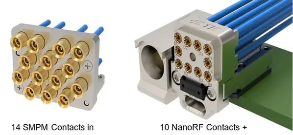
Fig. 2 - Here is an example of two VITA 67.3 RF I/O connector options (images courtesy of TE Connectivity)
It is also worth noting that VITA 67.3 does not currently define the explicit purpose of the individual RF I/O contacts on the backplane that connect to the 3U/6U PICs. The allocation of transmit antennas, receive antennas, or other specific analog RF/IF signal transceivers is up to the backplane vendor, and will be specific to a given vehicle deployment. There is some effort underway within the SOSA consortium to standardize the RF I/O allocation on the backplane, and future versions of the SOSA specification may incorporate this.
Limiting the RF I/O access to the backplane can present challenges, especially during the engineering/development phase of a product. It can also increase component cost for production systems, since the RF connectors typically used to connect the backplane to the plug-in card can be expensive. However, the benefit here is that the blindmate connection between the 3U/6U PIC installed on to the backplane ensures a consistent and reliable connection that doesn’t require a human to manually connect a coaxial cable (thus minimizing the chance for error). Further, front panel I/O can make it challenging to meet the environmental requirements mandated by SOSA, especially when RF cables would need to run from the front panel of one card to another card. Many 3U/6U VPX cards aligned to SOSA offer options to connect to RF I/O through the front panel for engineering/development purposes, and then transition to accessing RF I/O through the backplane in production.
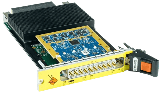
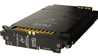
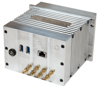
Fig. 3 - A complete 4x4 MIMO RF transceiver solution from Epiq Solutions
In the system pictured above, we have combined our Sidekiq X4 FMC card with an Annapolis Micro Systems 3U VPX FPGA-based carrier card. This platform can be used as shown with front panel I/O and convection cooling during development, and then transition to backplane I/O and conduction cooling for production.
RF Signals on the 3U/6U PIC...Now What?
In a SOSA-compliant chassis, the RF signals are received through the antenna and the chassis connects those signals to the backplane, where they are then distributed to the relevant 3U/6U PICs according to the VITA 67.3 specification. For cases where all of the RF hardware is directly integrated onto the 3U/6U PIC itself, low-loss semi-rigid RF cabling is often used to route the signals directly to the needed hardware. In cases where the RF hardware may be implemented in an FPGA mezzanine card (FMC) plugged into the 3U/6U VPX PIC, low-loss flexible RF coaxial cable can be used to route the signals to the required hardware.
In some cases, such as the Sidekiq X4-based transceiver solution shown in Figure 3, all of the RF receive/transmit functionality plus A/D and D/A conversion + FPGA signal processing can reside on a single 3U VPX card solution. In SOSA-aligned production variants, the RF signals need to route only from the backplane to this 3U VPX plug-in card once, where they are then cabled over to the FMC card. In other cases, the RF processing line-up may be split between multiple 3U/6U VPX cards, where one card serves as an RF tuner and another card performs analog to digital conversion. For example, a vendor may provide an RF receiver block conversion card in a 3U VPX form factor that provides frequency coverage from 6 GHz to 18 GHz. The antenna input exposed to the 6 to 18GHz RF signal would route from the chassis onto the backplane, and then onto this block conversion card through the VITA 67.3 interface. The block conversion card would then downconvert the RF signal to a much lower intermediate frequency (IF). This analog IF signal would then be routed back on to the backplane via the interface and passed over to appropriate 3U/6U VPX card to perform analog-to-digital conversion and subsequent processing. In deployments like this, where RF signals need to pass from one 3U VPX PIC to another 3U VPX PIC, the backplane must be designed to specifically accommodate this RF connection. An example block diagram of this architecture is shown in Figure 4 below.
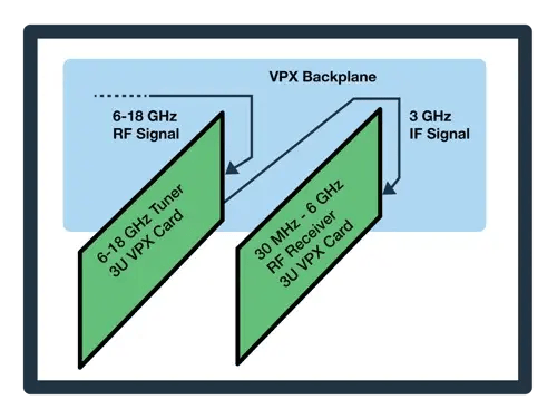
Fig. 4 - An example of a 3U VPX system with RF receiver capabilities split between two separate cards
Summary
Connecting high performance SOSA-aligned RF cards to the external antennas in a system is a critical piece of the equation when it comes to SIGINT, EW, radar, and comms. SOSA has defined connectors from bringing RF signals into the chassis, and leverages VITA 67.3 to define how RF signals route from the backplane onto the 3U/6U VPX plug-in cards. With a never-ending appetite for expanded RF frequency range and number of RF channels, continuing to focus on standards such as VITA 67.3 will hopefully provide a path to ensure RF cards can realize the goal of modular RF I/O within the SOSA ecosystem.